- Navigation Bar
- Contact Us
- Phone: +86-185 6192 1984
- Wechat: +86-185 6192 1984
- WA: +86-185 6192 1984
- Email:3003792189@qq.com

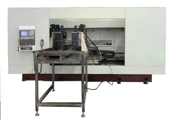
Double-Head Milling Machine
The double-head end milling machine is an automated machine tool specifically designed for symmetrical or asymmetrical milling operations on both ends of long, linear workpieces such as shafts, rods, and tubes. Its core feature is single-setup machining of both ends simultaneously, significantly enhancing production efficiency and consistency in machining accuracy.
Working Principle of Speed Control for Fully Automatic CNC Milling and Flattening Machines: The main unit of the fully automatic CNC milling and flattening machine employs a variable-speed motor drive equipped with a high-power reduction system, featuring soft start and soft stop for smooth operation.
The main unit of the fully automatic CNC milling machine employs a variable-speed motor drive equipped with a high-power reduction system, featuring soft start and soft stop for smooth operation. During processing, the upper and lower grinding discs, sun gear, and planetary gears coordinate to generate grinding motions in four directions at synchronized speeds, achieving simultaneous grinding of both upper and lower surfaces.
Automatic CNC Milling Machine Speed Control Method The grinding process comprises three phases: initial, formal, and final. During the initial phase, the grinding wheel accelerates to rotation speed, with acceleration exhibiting an inflection point. The acceleration controlling the wheel speed decreases gradually from its maximum value until the wheel reaches the formal grinding speed. In the formal phase, the wheel rotates at a constant speed, while in the final phase, it decelerates. During the initial grinding phase, the acceleration of the grinding wheel speed is manually controlled to increase gradually from zero. When the wheel speed reaches half of the formal grinding speed, the acceleration is reduced to zero.
By leveraging the characteristic of grinding with bonded abrasives, the density distribution of abrasives on the grinding wheel is rationally designed based on the relative motion trajectory density distribution between the workpiece and the wheel. This ensures that wear occurring during the grinding process does not compromise the surface profile accuracy of the wheel, thereby significantly improving the surface profile accuracy of the workpiece while eliminating the need for tedious wheel dressing. In planar bonded abrasive grinding, the rotational motion of the grinding wheel serves as the primary motion, while the movement of the workpiece functions as the auxiliary motion.
1. Core Configuration: Features a dual-head symmetrical milling layout equipped with Mitsubishi’s high-end CNC system and servo drive units. Utilizes carbide flat milling cutters with automatic compensation devices, optimizing cutting parameters for planar machining;
2. Ultimate Precision: Flat milling surface parallelism error ≤±0.015mm, surface roughness Ra≤1.6μm, flat position symmetry ≤0.02mm, meeting precision machining standards;
3. Doubled Efficiency: Dual-head synchronous cutting paired with a 4500rpm high-frequency spindle completes milling a single roller shaft in just 20-40 seconds. This delivers over 6 times the efficiency of traditional milling machines, with a single unit achieving daily output of 1500-2000 pieces;
4. Intelligent Adaptability: Supports various processing forms including single-flattened, double-flattened, and square-flattened profiles. Features an integrated library of over 100 process parameters for rapid switching between different product specifications. Compatible with roller shafts ranging from Φ16mm to Φ100mm in diameter and 200mm to 2200mm in length.
Primary Application Areas
Widely used in industries requiring high-volume, efficient machining of both ends of shaft-type components:
1. Automotive components: Valves, connecting rods, half-shafts, drive shafts, steering shafts, piston rods, etc.
2. Fasteners/standard parts: Double-end chamfering or square milling of bolts and screws.
3. Hydraulic and pneumatic components: Piston rods, cylinder rods, valve stems.
4. Motors and electrical appliances: motor shafts, rotor shafts.
5. Tools and hardware: various handles, tool holders, drill rods.
Working Principle and Processing Flow
1. Loading: Workpieces are placed into specialized fixtures manually or via automatic feeding mechanisms (vibratory feeders, conveyor belts, etc.).
2. Positioning and Clamping: Fixtures (typically V-blocks or elastic chucks) automatically center based on workpiece diameter. Workpieces are securely clamped to prevent movement during machining.
3. Synchronous Milling: Two milling spindles (spindle heads) move simultaneously and synchronously toward the workpiece center under CNC or PLC control. Following a preset program, operations such as milling flat surfaces and grooves are performed on both ends of the workpiece.
4. Retraction and Unloading: After machining is complete, the spindles retract, the fixture releases, and the finished workpiece is ejected or retrieved by a robotic arm, dropping into the finished parts bin to complete one cycle.